6 minutes
Cannon Instrument Company Internship
Overview
Over this past summer I have had the privilege to work at Cannon Instrument Company as an Electrical Engineering intern. Being my first full time job as an engineer, I learned more than I could have imagined. In this post, I would like to share some of my experiences.
The Beginning
Before I could start any real work at Cannon, I was first brought up to speed on company practices and tools that I would be needing throughout my internship:
- LTSpice: A free program which simulates circuits in a realistic way. This was a very useful tool for planning out schematics.
- Altium Designer: A popular PCB designer and ECAD program.
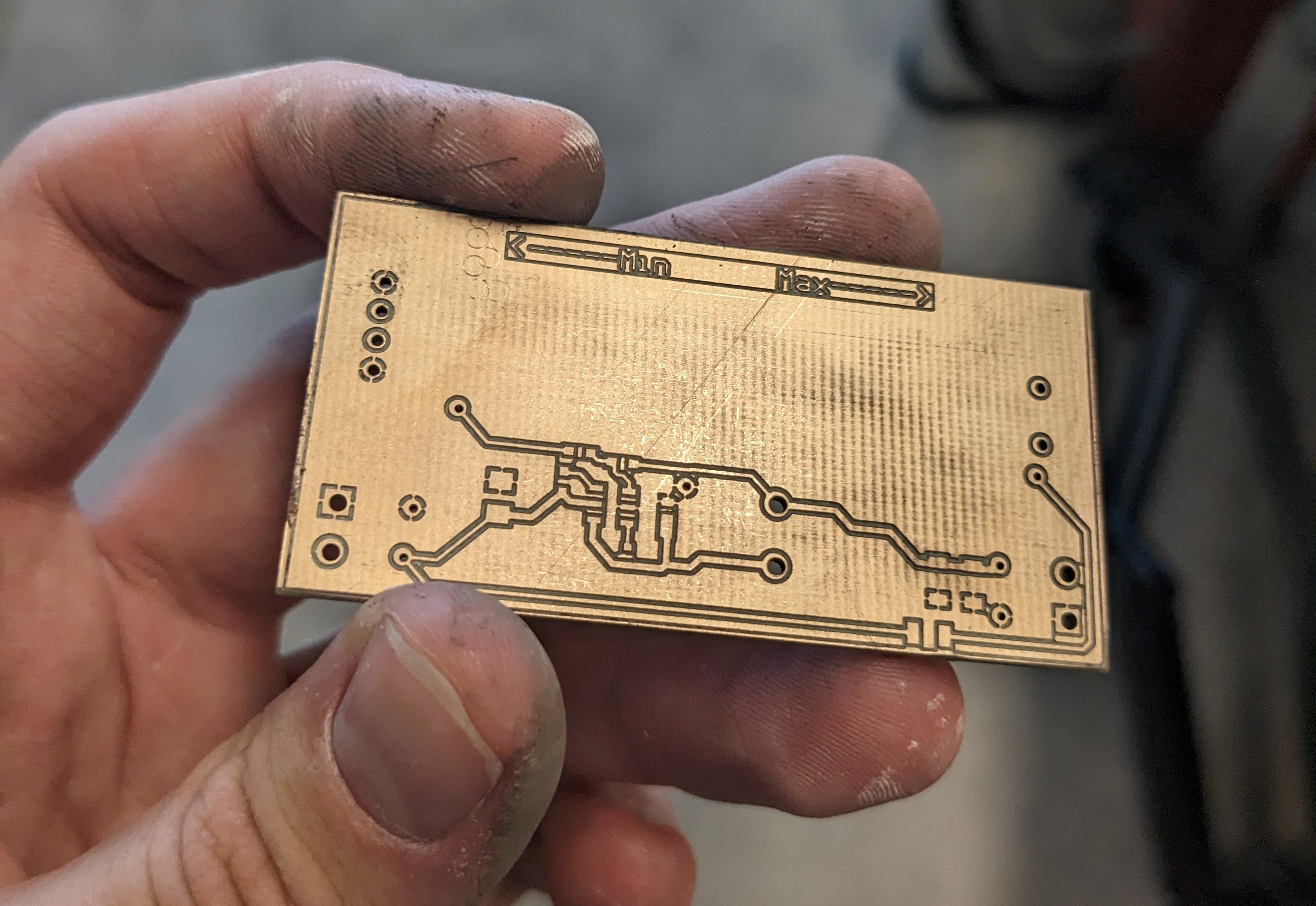
- PCB Milling: Cannon uses a prototyping mill. This mill prosses FR4 copper plates into PCBs that are good enough for protype testing.
These tools allowed me to complete my warmup project which consisted of making an adjustable power supply.

The Main Project
Finally, it was time to start the main project. To provide, some context: Cannon Instrument Company produces automated viscosity measuring devices (viscometers) alongside other scientific instruments. These viscometers use valves and an air pump to move fluid through their testing blocks. As such, these valves need to be reliable to get accurate readings.
To assess whether valves operate within specifications they need to be tested. Until now, these checks were done manually. The goal of the main intern project was to automate this process. We decided to call it the CICVT (Cannon Instrument Company Valve Tester).
To test the valves, we developed a three step prosses:
- Run several tests, where we test the characteristics of each valve. In each test, a pump changes the pressure on one side and measures the pressure on the other.
- The valves warm up for 15 minutes by staying open.
- Run the first step again on the warm valves. This checks how the valves perform under a heavy workload.
The CICVT Main Board
As the project’s electrical engineer, my job was to design a PCB that could actuate the valves that were being tested, and that integrates with the mechanical system. Additionally, I wrote the firmware to control the whole testing rig.
Shift Registers
I ran into the first hurtle rather quickly. We had decided that the CICVT would need to test up to 16 valves. Additionally, we would need a second valve bank to control which valve would be hooked up in the testing system. This meant that just to control the valves alone we needed 32 output pins.
This offered some challenge because the ESP-32 we were using didn’t have enough pins to control all the valves. As such we decided to put all the valves on shift registers. These shift registers took serial data and would convert it into up to 8 parallel digital outputs. The trick, however, is that after the first shift register fills up and can’t hold any more outputs it transmits the remaining serial data further. This means that you can chain these registers back-to-back with only a speed delay. The shift registers used SPI (serial peripheral interface) which meant we could control all 32 valves from only four pins.
To me, the easiest way to conceptualize this is by thinking of a conveyor belt. Imagine each shift register as one part of a track of conveyer belts. Then, each bit of data as an item on this conveyer belt. You can always extend the conveyer belt by one more section, it will just take a little longer for the data to reach it.
Presence detection
Another key feature is that the machine automatically detects what valves are plugged in and where they are. Below is a circuit diagram.

The idea of the circuit is rather simple and works on the concept that a valve is basically just a coil. The whole circuit consists of measuring the voltage along the top node. Looking at the diagram in its current state, the node is being pulled high by a 100k ohm pull up resistor. However, there is a path to ground through a 10k ohm resistor and an LED. In this application the forward voltage of the LED acts as a Zener diode and keeps the pres_det_1 node at 3.3 volts. However, when a valve connects the two legs of J1 (the connector) the node is pulled down to ground, and the pres_det_1 node goes to 0 volts.
This has the additional advantage of providing the user with a light to indicate whether the valve is properly plugged in.
Prototyping
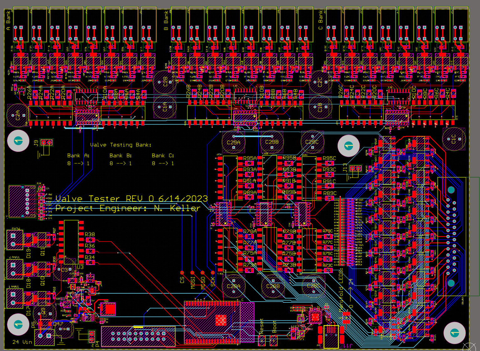
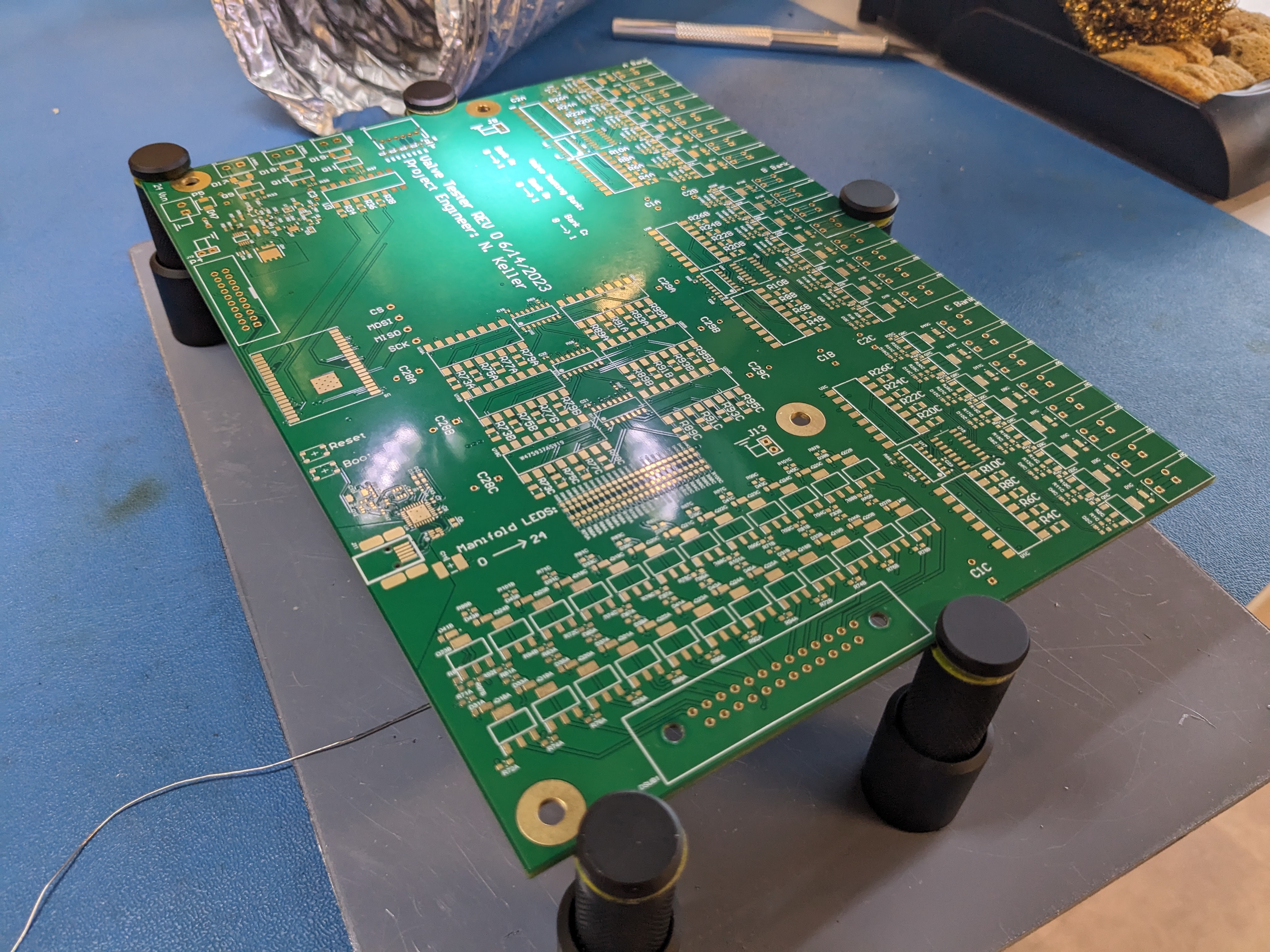
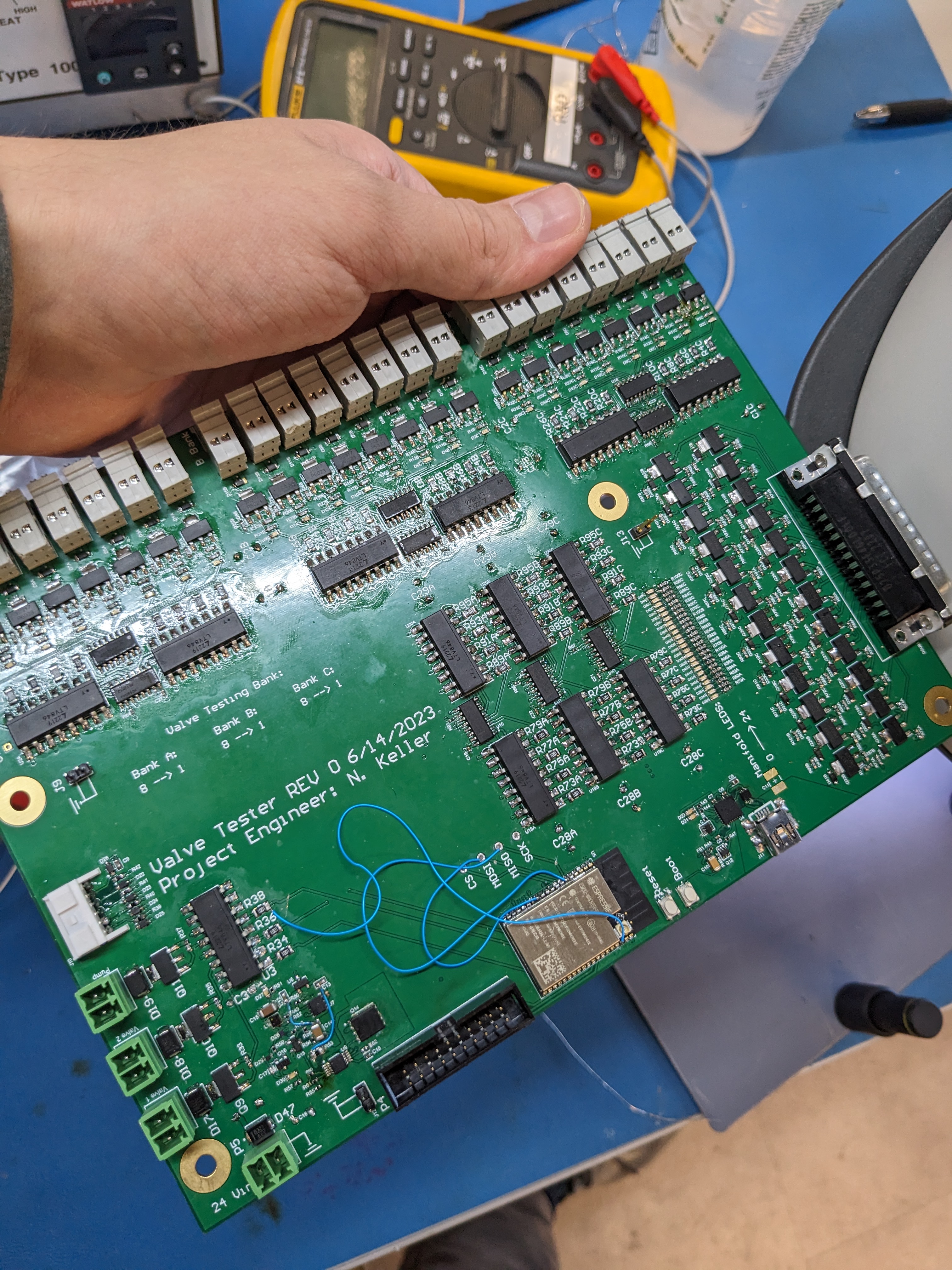
With the previous examples as well as some other sub systems finished it was finally time to layout and order the board. The board was then ordered and assembled. Below are pictures of the first iteration.


As expected, the first board didn’t quite work. While functional, there were some errors which are visible as blue jumpers on the assembled board. There was one larger issue that didn’t allow one of the SPI busses to be released. This meant that the touch screen didn’t work. While the first board didn’t fully work, it still functioned with an external console connected to the ESP32, so I am rather pleased with the results.
As I was the one hand soldering the board, I was quite satisfied to see it all come together. Getting each subsystem up and running proved to take much longer than I had expected, yet it was great to see my efforts pay off. My final task before finishing my internship was creating a revision which fixed the issues of the previous board, and fully documenting my circuits and code for someone else to take over.
Conclusion
Having the privilege of working at Cannon has taught me more than I would have thought possible in such a short time. Not only was I able to apply my classroom learning to a real-world project, but I also learned many new concepts and ideas. Furthermore, I had access to resources to try my ideas, and to test them with industrial equipment. I had a great experience at Cannon, and I plan to take my new skills with me in my career.
Note: All the photos used in this post are used with permission from Cannon Instrument Company. Additionally, while it has come to my attention that some have migrated away from SPI bus names like MISO and MOSI, I followed Cannon’s naming scheme on the silkscreen.
Gallery:
Finally, I just wanted to leave you with some photos of various parts and prototype boards used during my internship.
1165 Words
2023-08-18 17:50


